Tuesday, January 12, 2010

Tips for utilizing 3GPP specification


If you have something about which you have no idea of what they are talking about, you would ask somebody else for explanation.. and usually what you think is expert would give you very brief explanation which would not help you much and say "Refer to the 3GPP spec AA.BBB for the detailed explanation". So you download and open the specification AA.BBB and start reading. Does this help ? In most case, NO. If you read the spec AA.BBB and it also says in similar way as your expert did, meaning "giving you a minimum description and saying 'refer to spec BB.CCC" and if you gets into the spec BB.CCC.. you will get into the same situation. This would be the first frustration when you try to understand based on the 3GPP specification.

Is there any easy solution for this ? Honestly and unfortunately, NO. But one thing that may help you in long term would be to understand relationships among multiple specifications.
Pick a specific area where you are specially interested in and make a list of additional specification and define the relationship among those specification. I have a couple of examples here.

Tips for myself.

Currently I am pretty heavily involved in writing test cases for Physical Layer and Higher Layer Signaling (RRC/NAS) and the following is 3GPP standards that I frequently refer to. This may or may not help you much.. but I keep this for my own quick reference.

  • Overall RRC Protocol - TS36.331
  • NAS : EPS - TS 24.301, TS 29.274
  • NAS : QoS Related - TS 23.203 (Policy and Charging Control Architecture)
  • DCI Format - 36.213 7.1 UE procedure for receiving the physical downlink shared channel
  • Transport Block Size and Throughput Calculation - TS36.213 Table7.1.7.1-1

PUCCH Reference Signal

  • TS 36.211 - 5.4 Physical uplink control channel
  • TS 36.211 - 5.4.1 PUCCH formats 1, 1a and 1b
  • TS 36.211 - 5.4.3 Mapping to physical resources
  • TS 36.211 - 5.5.1.3 Group hopping
  • TS 36.211 - 5.5.2.2 Demodulation reference signal for PUCCH
  • TS 36.211 - 5.5.2.2.1 Reference signal sequence
  • TS 36.212 - 5.2 Uplink transport channels and control information
  • TS 36.212 - 5.2.3 Uplink control information on PUCCH
  • TS 36.213 - 10.1 UE procedure for determining physical uplink control channel assignment
  • TS 36.331 - 6.3.2 Radio resource control information elements - PUCCH-Config

PUSCH

  • TS 36.211 - 5.5.2.1 Demodulation reference signal for PUSCH
  • TS 36.212 - 5.2 Uplink transport channels and control information
  • TS 36.212 - 5.2.2 Uplink shared channel
  • TS 36.212 - 5.2.3 Uplink control information on PUCCH
  • TS 36.331 - 6.3.1 System information blocks – SystemInformationBlockType2
  • TS 36.331 - 6.3.2 Radio resource control information elements – PUSCH-Config

PHICH

  • TS 36.211 - 6.9 Physical hybrid ARQ indicator channel
  • TS 36.213 - 8.3 UE ACK/NACK procedure
  • TS 36.213 - 9.1.2 PHICH Assignment Procedure
RACH Procedure

  • TS36.211 - 5.7 Physical random access channel
  • TS36.211 - Table 5.7.1-2 Frame structure type 1 random access configuration for preamble format 0-3.
  • TS36.331 - 6.3.1 System information blocks – SystemInformationBlockType2
  • TS36.331 - 6.3.2 Radio resource control information elements - PRACH-Config
  • TS36.331 - 6.3.2 Radio resource control information elements - RACH-ConfigCommon
  • TS36.331 - 6.3.2 Radio resource control information elements - RACH-ConfigDedicated
Paging Procedure

  • TS 36.304 - 7 Paging

CCE Index Calcuation
  • TS 36.213 - 9.1.1 PDCCH Assignment Procedure

Specifications for UE conformance Testing

If you want to know the details of Conformance Test for LTE, you need to refer to the specification listed at http://www.3gpp.org/ftp/Specs/html-info/36-series.htm

Even though you are not in the conformance type of testing, a lot of IOT (Inter Operability Test) and any user defined test cases has similar concept to the conformance. So trying to understand the conformance testing would help you understand any type of testing.

The first set of specification you have to be familar with are as follows :


  • 36.521-1 : RF Conformance (Transmitter Test, Reciever Test and Performance Test)
  • 36.521-3 : RF Conformance (RRM Test)
  • 36.523 : Protocol Conformance
    • When you read these specification, they would describe only test purpose/expected result and overal procedure, but does not describe details of protocol sequence and IE(information elements) for each of the Layer 3 messages. Regarding these, you have to refer to


      • 36.508 : UE Test Environment
      • 36.101 : UE TxRx

      For example, if you want to understand the procedure about "LTE Transmit Power" Measurement, the first thing you will look into will be the following description of 36.521.

      ** 6.2.2.4.1 Initial Condition **
      1. Connect the SS to the UE antenna connectors as shown in TS 36.508[7] Annex A Figure A3.
      2. The parameter settings for the cell are set up according to TS 36.508 [7] subclause 4.4.3.
      3. Downlink signals are initially set up according to Annex C.0, C.1, and C.3.0, and uplink signals according to Annex H.1 and H.3.0.
      4. The UL Reference Measurement channels isset according to Table 6.2.2.4.1-1.
      5. Propagation conditions are set according to Annex B.0.6. Ensure the UE is in State 3A according to TS 36.508 [7] clause 4.5.3A. Message contents are defined in clause6.2.2.4.3.

      ** 6.2.2.4.2 Test procedure **
      1. SS sends uplink scheduling information every TTI via PDCCH DCI format 0 for C_RNTI to schedule the ULRMC according to Table 6.2.2.1.4.1-1. Since the UE has no payload and no loopback data to send the UE sendsuplink MAC padding bits on the UL RMC
      2. Send continuously uplink power control “up” commands in the uplink scheduling information to the UE until theUE transmits at its maximum output power state according to the test configuration from Table 6.2.2.4.1-1.
      3. Measure the mean power of the UE in the channel bandwidth of the radio access mode. The period ofmeasurement shall be one sub-frame (1ms).

      Just for overall test procedure, the information described above would be enough even without refering to other specification or table. But if you have to do the troubleshooting of the failed test/test error or if you are an engineer who has to develop the test cases, you should not miss even a tiny particles out of all of the following items which was refered in the procedure.


      • TS 36.508 Annex A Figure A3
      • TS 36.508 subclause 4.4.3.
      • TS 36.521 Annex C.0, C.1, and C.3.0
      • TS 36.521 Annex H.1 and H.3.0
      • TS 36.521 Table 6.2.2.4.1-1
      • TS 36.508 clause 4.5.3A
      • TS 36.521 Table 6.2.2.1.4.1-1

      If you want to know the protocol sequence during the test case execution, you have to refer to TS 36.508 section "4.5 Generic Procedure"

      Then you need to know the contents (IE : Information Elements) of each message which is described in 36.508 section 4.6, 4.7, 4.7A.

      Isn't this complicated enough to make your head spinning ? -:) But once you got into this area, you would never survive without being familiar with this documents and struggling with them.


      Friday, January 8, 2010

      Tips for LTE TTCN Source


      Where can I get TTCN and Viewer ?

      This is where you can download the TTCN source code from
      http://www.3gpp.org/ftp/tsg_ran/WG5_Test_ex-T1/TTCN/Deliveries/LTE_SAE/

      You can download free TTCN-3 Viewer from
      http://www.eu.anritsu.com/ttcn

      Where do I have to start ?

      If you open up the TTCN source, it would look extremly complicated and I don't know where to start to look at. Where do I have to start ?

      If you want to have overall understanding of test procedure/protocol sequence of each test case, I think it would be better to look at test case description in 3GPP 36.523-1. But when you go over the test procedure over and over, I would start further details of parameters and it's default values of the IE (information elements) for the test cases. I would start with EUTRA_RRC_ASN1_Definitions.asn in CommonEUTRA_Def folder.


      Understand RACH !

      What is the most tricky part in device troubleshooting ? My experience says "If a problem happens in the middle of doing something, it is relatively easy to find the root cause and troubleshoot it (probably I might have over-simplified the situation -:), but if something happened before anything started, it would be a nightmare." For example, you set the all the parameters at the network emulator for a UE you want to test and then turned on the UE. In a several second UE start booting and then in a couple of second you see a couple of antenna bars somewhere at the top of UE screen.. and then in several seconds you see 'SOS' or 'Service Not Available' in stead of your network operator name displayed on your screen and normal Antenna bars. This is what I mean by "problem in the middle of doing something". In this case, if you collect UE log and equipment log, at least you can easily pin point out the location the problem happens and start from there for further details. But what if you are in this situation ? you set the all the parameters at the network emulator side and turn on the UE.. UE start booting up .. showing the message saying "Searching Network ...." and got stuck there.. with no Antenna bars .. not even 'SOS' .. just saying "No service". And I collected UE side log and Network Emulator side log, but no signalling message. This is where our headache starts.


      As examples,


      i) What if you don't see 'RRC Connection Request' when your turned on the WCDMA UE ?


      ii) What if you don't see 'Channel Request' when your turned on the GSM UE ?


      iii) What if you don't see 'RACH Preamble' when your turned on the LTE UE ?


      First thing you have to do is to understand the every details of this procedure not only in the higher signaling layer, but also all the way down to the physical layers related to these first step. And also you have to use proper equipment which can show these detailed process. If you have an equipment that does not provide the logging or it provides log but only higher layer singnaling log, it will be extremly difficult to troubleshoot. Given that you have the proper tools, the next thing you have to be ready is to understand the detailed knowledge of these process. Without the knowledge, however good tools I have it doesn't mean anything to me. So ? I want to teach myself here about the first step of LTE signaling which is RACH process. (Somebody would say there are many of other steps even before the RACH, like frequency Sync, Time Sync, MIB/SIB decoding.. but it put these aside for now.. since it is more like baseband processing).


      When RACH Process occurs ?


      It would be helpful to understand if you think about when 'RRC Connection' happens (or when PRACH process happens if you are interested in lower layer stuffs) in WCDMA. It would also be helpful if you think about when 'Channel Request' happens in GSM UE.


      My impression of LTE RACH process is like the combination of PRACH process (WCDMA) and Channel Request (GSM). It may not be 100% correct analogy.. but anyway I got this kind of impression. In LTE, RACH process happens (The following list came from the LTE training manual by Award Solution. Of course, this description is also based on 3GPP specification)


      i) During initial access to register or RRC Connection Request


      ii) When a radio link failure occurs during the initial access


      iii) During the Handover to allocate the scheduling grant from the target eNB


      iv) UL synchronisation is lost


      v) When there are no dedicated resources (no PUCCH resources have been assinged to UE).


      Two types of RACH process : Contention-based and Contention-free


      When a UE transmit a PRACH Preamble, it transmits with a specific pattern and this specific pattern is called a "Signature". In each LTE cell, total 64 preamble signatures are available and UE select randomly one of these signatures.


      UE select "Randomly" one of these signatures ?


      Does this mean that there is some possibility that multiple UEs send PRACH with identical signatures ?


      Yes.


      There is such a possibility. It means the same PRACH preamble from multipe UE reaches the NW at the same time.. this kind of PRACH collision is called "Contention" and the RACH process that allows this type of "Contention" is called "Contention based" RACH Process. In this kind of contention based RACH process, Network would go through additional process at later step to resolve these contention and this process is called "Contention Resolution" step.


      But there is some cases that these kind of contention is not acceptable due to some reason (e.g, timing restriction) and these contention can be prevented. Usually in this case, the Network informs each of the UE of exactly when and which preamble signature it has to use. Of course, in this case Network will allocate these preamble signature so that it would not collide. This kind of RACH process is called "Contention Free" RACH procedure. To initiate the "Contention Free" RACH process, UE should be in Connected Mode before the RACH process as in Handover case.


      Typical 'Contention Based' RACH Procedure is as follows :


      i) UE --> NW : RACH Preamble (RA-RNTI, indication for L2/L3 message size)


      ii) UE <-- NW : Random Access Response (Timing Advance, T_C-RNTI, UL grant for L2/L3 message)


      iii) UE --> NW : L2/L3 message iv) Message for early contention resolution


      Now let's assume that a contention happened at step i). For example, two UEs sent PRACH. In this case, both of the UE will recieve the same T_C-RNTI and resource allocation at step ii). And as a result, both UE would send L2/L3 message through the same resource allocation(meaning with the same time/frequency location) to NW at step iii). What would happen when both UE transmit the exact same information on the exact same time/frequency location ? One possibility is that these two signal act as interference to each other and NW decode neither of them. In this case, none of the UE would have any response (HARQ ACK) from NW and they all think that RACH process has failed and go back to step i). The other possibility would be that NW could successfully decode the message from only one UE and failed to decode it from the other UE. In this case, the UE with the successful L2/L3 decoding on NW side will get the HARQ ACK from Network. This HARQ ACK process for step iii) message is called "contention resolution" process.


      Typical 'Contention Free' RACH Procedure is as follows :


      i) UE <--NW : RACH Preamble Assignment


      ii) UE --> NW : RACH Preamble (RA-RNTI, indication for L2/L3 message size)


      iii) UE <--NW : Random Access Response (Timing Advance, C-RNTI, UL grant for L2/L3 message)


      Exactly when a UE transmit RACH ?


      To answer to this question, you need to refer to 3GPP specification TS36.211 - Table 5.7.1-2.


      Did you open the specification now ? It shows exactly when a UE is supposed to send RACH depending on a parameter called "PRACH Configuration Index".


      For example, if the UE is using "PRACH Configuration Idex 0", it should transmit the RACH only in EVEN number SFN(System Frame Number). Is this good enough answer ? Does this mean that this UE can transmit the RACH in any time within the specified the SFN ? The answer to this question is in "Sub Frame Number" colulmn of the table. It says "1" for "PRACH Configuration Idex 0". It means the UE is allowed to transmit RACH only at sub frame number 1 of every even SFN.


      Checking your understanding of the table, I will give you one question. With which "PRACH Configuration Idex", it would be the easiest for the Network to detect the RACH from UE ? and Why ?


      The answer would be 14, because UE can send the RACH in any SFN and any slots within the frame.


      How does Network knows exactly when UE will transmit the RACH ?


      It is simple. Network knows when UE will send the RACH even before UE sends it because Network tells UE when the UE is supposed to transmit the RACH. (If UE fails to decode properly the network information about the RACH, Network will fail to detect it even though UE sends RACH).


      Following section will describe network informaton on RACH.


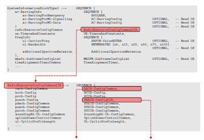
      Which RRC Message contains RACH Configuration ?


      It is in SIB2 and you can find the details in 3GPP 36.331. (Click the image to enlarge it so that you read it clearly)


      Exactly when Network transmit RACH Response


      We all knows that Network should transmit RACH Response after it recieved RACH Preamble from UE, but do we know exactly when, in exactly which subframe, the network should transmit the RACH Response ? The following is what 3GPP 36.321 (section 5.1.4) describes.


      Once the Random Access Preamble is transmitted and regardless of the possible occurrence of a measurement gap, the UE shall monitor the PDCCH for Random Access Response(s) identified by the RA-RNTI defined below, in the RA Response window which starts at the subframe that contains the end of the preamble transmission [7] plus three subframes and has length ra-ResponseWindowSize subframes.


      It means the earliest time when the network can transmit the RACH response is 3 subframe later from the end of RACH Preamble. Then what is the latest time when the network can transmit it ? It is determined by ra-ResponseWindowSize. This window size can be the number between 0 and 10 in the unit of subframes. This means that the maximum time difference between the end of RACH preamble and RACH Response is only 12 subframes (12 ms) which is pretty tight timing requirement.


      RACH Procedure during Initial Registration - RACH Procedure Summary


      Follwing is an example of RACH procedure which happens during the initiail registration. If you will be an engineer who is working on protocol stack development or test case development, you should be very familiar with all the details of this process.


      Again, we have to know every details of every step without missing anything to be a developer, but of course it is not easy to understand everything at a single shot. So, let's start with something the most important part, which I think is the details of RACH response. Following diagram shows one example of RACH Response with 5 Mhz bandwidth. We don't have to memorize the detailed value itself but should be familiar with the data format and understand which part of this bit string means what. If you decode UL Grant part, you will get the following result. You will notice that the information it carries would be very similar to DCI format 0 which carries Resource Allocation for uplink data. This information in UL Grant in RACH Response message is the resource allocation for msg3 (e.g, RRC Connection Request).


      Let me describe this procedure in verbal form again.


      i) UE initiate a Random Access Procedure on the (uplink) Random Access Channel (RACH).(The location of RACH in the frequency/time resource grid the RACH is known to the mobile via the (downlink) Broadcast Channel (BCH). The random access message itself only consists of 6 bits and the main content is a random 5 bit identity)


      ii) Network sends a Random Access Response Message(RARM) at a time and location on the Physical Downlink Shared Channel (PDSCH) (The time and location of RARM on PDSCH can be calculated from the time and location the random access message was sent. This message contains the random identity sent by the device, a Cell Radio Network Temporary ID (T_C-RNTI) which will be used for all further bandwidth assignments, and an initial uplink bandwidth assignment)


      iii) The mobile device then uses the bandwidth assignment to send a short (around 80 bits) RRC Connection Request message which includes it's identity which has previously been assigned to it by the core network


      Only the step i) uses physical-layer processing specifically designed for random access. The remaining steps utilizes the same physical layer processing as used for normal uplink and downlink data transmission


      3GPP Standard for RACH Process


      3GTS 36.300 (10.1.5) : Overall description of RACH Process. Read this first.


      3GTS 36.211 (5.7) : RRC Messages and IE (Information Elements) which are involved in RACH process.


      3GTS 36.213 (6) : MAC Layer Procedure related to RACH Process.


      Thursday, January 7, 2010

      LTE Downlink Signal Constellations

      Click the image to enlarge

      Look through the constellations and control channel(CCH) and Share Channel(SCH) configuration.. and see how the constellation changes depending on the configuration.

      Why only pictures ? It is to give you something to think about.

      All of these example are from the measurement result of the transmitted from a LTE Network emulator transmitting with full Resource Block allocation across all the subframes. If you see the first three example, they are all MCS 9 which is QAM. Why the constellation are different from each other ? Even in the same example, why slot 0 constellation is different from other slots ? Why are there some additional dots (constellation) in slot 5 and 6 ?

      Try to correlate the map explained at http://jaekuryu.blogspot.com/2010/01/first-thing-you-have-to-be-familiar.html with the constellation shown here. If you can freely pull up the channel map and these constellation in your brain and draw correlation line between the map and the constellation, you are in a good position to understand the physical entity of LTE signal. Practice ! Practice ! Practice.

      CCH = Single, SCH = Single, MCS = 9 (QAM)

      The seven constellation corresponds to the first slot of a sub frame. (Can you pull up the channel map in your brain ? If not, see the channel map again). Symbol 1 corresponds to the control channel (PDCCH) (In LTE, control channel in each subframe can use maximum 3 symbols, but for this tutorial I configured the number of slots for the control channel to be 1. So in this constellation, only symbol 1 is for control channel and all the other symbols are for data (PDSCH) (of course, small portions of these parts are used for Sync channel and PBCH).

      In symbol 5 and 6, you see a couple of other dots (constellation) which look different from the other symbols (symbol 2-4). What would they are ? We would need further study to figure out exactly what they are, but just based on the channel map poping up in your brain now.. you would see these strage looking dots would come from Primary Sync, Secondary Sync). You don't have to know everything at once, just try to accumulate knowledge one by one.


      The constellations shown above is for symbol 7-13. These are all for PDSCH (data) and I configured all the slot with the same data format, so you don't see any differences among these constellations.

      This is very brief explantion of the constellation of one subframe (subframe 1) of LTE downlink signal. It may sound too superficial, but trying to explain the other constellations listed below in the way I explanined here would allow you to be more familiar to LTE PHY signals.


      CCH = SFBC, SCH = Single, MCS = 9 (QAM)


      CCH = Single, SCH = MIMO, MCS = 9 (QAM)


      CCH = SFBC, SCH = MIMO, MCS = 23 (64QAM)

      LTE Basic Procedures

      You can use this section as a kind of dictionary explaining fundamental concept of various signaling components. Topics described here are as follows and more topics will be added.

      • Fundamental Information
      • Initialization Sequence
      • Primary and Secondary Secondary Sync
      • Time Sync Process
      • Cell ID Detection
      • System Informations
      • Random Access
      • Uplink Data Transmission Scheduling - Persistent Scheduling

      Fundamental Information

      UE Capability : UE Category, Frequency Band, Sync Signal Sequence, General Radio Resource Info, General MIMO Parameter, Duplex Mode, Preamble sequence generation algorithm

      SIM : Network Operator's PLMN list, Subscription Information

      Stored Information : Most recently used frequency band, PLMN, Tracking Area Code, Cell ID, S-TMSI, InterRAT Frequency Band

      Information that UE needs to get: Frequency and Timing Synchronization info, System Bandwidth, Number of MIMO Antennas, Identities (C-RNTI, Physical Cell ID, Tracking Area Code), Network PLMN, Signaling & Traffic Radio Resouce, RACH_ROOT_SEQUENCE & PRACH Config.

      Initialization Sequence

      i) Power-Up Test
      ii) Frequency & Time and Frame Synchronization
      iii) Decode System Information Message
      iv) Select Prefered Network
      v) Perform RACH Process
      vi) RRC Connection Setup

      Frequency Aquisition

      i) Search the center frequency by searching DC part
      ii) Decode BCH which occupies 62 subcarriers (6 RBs) at the center frequency.
      iii) BCH tells the frequency information of the system (eg. System Frequency Bandwidth)

      Primary and Secondary Secondary Sync

      i) Each cell transmit one of 162 unique sequences on its secondary sync channel (each bit sequence is 62 bit sequence)
      ii) The seconday Sync code is one of three unique sequence (62 bit Zadd-off chu sequence) which is carried by Primay Sync
      iii) So total number of ID become 162 x 3 = 504

      Time Sync Process

      i) UE decode Primary sync with three different Primary Sync Sequence and figure out which sequence is assigned for the cell and abtain the primary time sync as well.
      ii) Apply the primary sync sequence with the Secondary Sync code and figure out which sequence is assigned for the cell.

      This Sync detection is done every 5 ms. (You will understand this time interval if you look at the LTE Downlink frame structure explained at http://jaekuryu.blogspot.com/2010/01/first-thing-you-have-to-be-familiar.html)

      As I mentioned in previous section, three different sequences are used as the primary sync signal and there is a one-to-one mapping between each of the three sequences and the cell ID within the cell identity group. After a UE detect this cell-identity group, it can determine the frame timing. From this cell identity group, the UE also figure out which pseudo-random sequence is used for generating the reference signal in the cell.

      Cell ID Detection and System Information Detection

      i) Frequency Aquisition
      ii) Primary Sync Signal Aquisition (Slot Timing Aquired, Secondary Sync Signal Scrambling Code Aquired)
      iii) Secondary Sync Signal Aquisition (Frame timing Aquired, Cell Group ID sequence aquired)
      iv) with PSS and SSS, Cell ID can be calculated
      v) with Cell ID, Reference Signal Location is detected
      vi) If Reference Signal Location is properly decoded, PBCH (MIB) can be detected
      vii) From MIB, SFN and System BW can be detected
      viii) Decode PCFICH and detect how many symbols are allocated for PDCCH.
      ix) Decode DCI for SIB1 from PDCCH
      x) Decode SIB1 and get the scheduling information for other SIBs
      xi) Decode SIBs (other than SIB1)

      One of the most important step for testing/troubleshooting around the initial registration is to check whether UE successfully complete the time-sync (step i) and ii)), but it is very hard to check this step with any kind of equipment. One way to easily check whether UE succeeded in time-sync or not is to check from UE log whether UE successfuly decoded Cell ID or not. If UE successfully detected Cell ID, it means UE successfully completed the time-sync.

      System Information

      MIB
      i) DL Bandwidth, Number of Transmit Antenna, Reference Signal Transmit Power
      ii) System Frame Number (SFN)
      iii) PHICH Configurationiv) Transmit every 40 ms , repeat every 10 ms

      MasterInformationBlock ::= SEQUENCE {
      dl-Bandwidth ENUMERATED { n6, n15, n25, n50, n75, n100},
      phich-Config PHICH-Config,
      systemFrameNumber BIT STRING (SIZE (8)),
      spare BIT STRING (SIZE (10))
      }

      SIB 1
      i) Cell Access Related Information - PLMN Identity List, PLMN Identity, TA Code, Cell identity & Cell Status
      ii) Cell Selection Information - Minimum Receiver Level
      iii) Scheduling Information - SI message type & Periodicity, SIB mapping Info, SI Window length

      SIB 2
      i) Access Barring Information - Access Probability factor, Access Class Baring List, Access Class Baring Time
      ii) Semi static Common Channel Configuration - Random Access Parameter, PRACH Configuration
      iii) UL frequency Information - UL EARFCN, UL Bandwidth, additional emmission

      Random Access

      Random Access process plays two main roles - establishment of uplink synchronization and establishment of a unique UE ID (C-RNTI) known to both the network and the UE.So Random Access is used not only for initial access, but also after periods of uplink inactivity when uplink sync got lost in LTE_ACTIVE states.

      i) UE initiate a Random Access Procedure on the (uplink) Random Access Channel (RACH).(The location of RACH in the frequency/time resource grid the RACH is known to the mobile via the (downlink) Broadcast Channel (BCH). The random access message itself only consists of 6 bits and the main content is a random 5 bit identity)
      ii) Network sends a Random Access Response Message(RARM) at a time and location on the Physical Downlink Shared Channel (PDSCH) (The time and location of RARM on PDSCH can be calculated from the time and location the random access message was sent. This message contains the random identity sent by the device, a Cell Radio Network Temporary ID (C-RNTI) which will be used for all further bandwidth assignments, and an initial uplink bandwidth assignment)
      iii) The mobile device then uses the bandwidth assignment to send a short (around 80 bits) RRC Connection Request message which includes it's identity which has previously been assigned to it by the core network

      Only the step i) uses physical-layer processing specifically designed for random access. The remaining steps utilizes the same physical layer processing as used for normal uplink and downlink data transmission.

      For further details of Random Access process, refer to http://jaekuryu.blogspot.com/2010/01/understand-rach.html

      Uplink Data Transmission Scheduling - Persistent Scheduling

      There are a couple of Data Transmission Scheduling Scheme in LTE. The most simple in terms of algorithm would be the persisent scheduling. In this scheduling mode, Network send 'Grant' in DCI Format 0 for every one subframe.

      i) Network send the first data on DL PDSCH and PDCCH which has DCI format 1 for DL Data Decoding and DCI format 0 for UL Grant. (If there is no downlink data to be transmitted, network transmits only DPCCH with DCI format 0 without any DPSCH data)
      ii) UE decode PCFICH to figure CFI value.
      iii) UE decode PDCCH and get the information on DCI format 1
      iv) Based on DCI format 1, UE decode DL data.
      v) UE decode the information on DCI format 0 from PDCCH
      vi) UE send ACK/NAK for DL data through UCI (UCI will be carried by PUCCH)
      vii) UE check the Grant field.
      viii) If Grant is allowed, UE transmit the uplink data through PUSCH
      ix) Network decode PUSCH data and send ACK/NACK via PHICH
      x) UE decode PHICH and retransmit the data if PHICH carries NACK
      For detailed data structure of DCI Format 0, refer to TS 36.212 section "5.3.3.1.1 Format 0"

      The process listed above is in reality a pretty complicated process and need a lot of troubleshoot and debugging. So in case of development and testing phase, we normally break down this process into multiple simple/small procedure and verifies it step by step.

      Step 1 : DL data reception and no ACK/NACK transmission ==

      a) Network send PDCCH and PDSCH data
      b) See if UE properly decode PDSCH data
      This would seem to be very simple two step process, but to make this happen UE is capable of doing step ii), iii), iv) described above.

      Step 2 : DCI format 0 reception ==

      a) Network send DCI Format 0(UL Grant) without PDSCH transmission
      b) See if UE properly decode DCI Format 0 (You need to make it sure that Resource allocation that UE decoded matches with DCI format 0 sent by network.)


      Step 3 : PUSCH transmission based on DCI format 0 ==

      a) Network send DCI Format 0(UL Grant) without PDSCH transmission
      b) UE transmit UL Data on PUSCH
      c) Network decode PUSCH data
      d) see if the data decoded at Network side maches what UE transmit
      To make this happen, UL DMRS for PUSCH should have been properly implemented and you have to make it sure that UE transmit the PUSCH data on the RBs that DCI format 0 specified.

      Step 4 : DL data reception and ACK/NACK transmission ==

      a) Network send PDCCH and PDSCH data
      b) UE decode PDSCH data
      c) UE has to transmit ACK/NACK accordingly

      Step 5 : UL data transmission and ACK/NACK reception ==

      a) Network send DCI Format 0(UL Grant) without PDSCH transmission
      b) UE transmit UL Data on PUSCH
      c) Network decode PUSCH data
      d) Network send ACK/NACK on PHICH
      e) UE has to decode ACK/NACK properly
      f) UE has to retransmit the data if it gets NACK

      Decoding Uplink Signal

      'Decoding Uplink Singal' means 'decoding PUCCH and PUSCH'. But eNode be normally get Uplink signal from multiple UEs and each of the UE may be in different distance and under different channel condition. So docoding uplink channel would not be easy. To help eNode be decode these uplink channel, UE transmit a reference signal.

      There are a few different uplink signal as listed below.
      i) DMRS (DeModulation Reference Signal) for PUCCH
      ii) DMRS (DeModulation Reference Signal) for PUSCH
      iii) Sounding Reference Signal.

      Item iii) would not be a mandatory component, but UE must send item i) and ii). Otherwise, eNodeB fail to decode PUCCH or PUSCH even though UE transmit it in proper format.

      Detailed implementation of UL reference signal is described in TS 36.211 section 5.5 and TS 36.213. You will notice a lot of parameters are involved in UL reference signal generation and the following is brief list of these parameters.

      * n_1_pucch : N(1)PUCCH described in 3GPP TS36.213
      * GroupHopping : 5.5.1.3 in TS36.211
      * Cell ID :
      * Pucch format : 5.5 in TS36.211
      * N_1_CS :
      * N_2_RB :
      * delta Pucch shift :
      * RNTI :
      * UL CP Configuration :
      * systemBW :
      * u_even : sequence-group number even slot (TS36.211 5.5.1.3)
      * u_odd : sequence-group number odd slot (TS36.211 5.5.1.3)
      * n_cs_even#0~#6 : Cyclic Shift for even slot in a subframe (TS36.211 5.4.1, 5.5.2.2.1)
      * n_cs_odd#0~#6 : Cyclic Shift for odd slot in a subframe (TS36.211 5.4.1, 5.5.2.2.1)
      * n_oc_bar_even : orthogonal sequence for even slot in a subframe (TS36.211 5.5.2.2.1)
      * n_oc_bar_odd : orthogonal sequence for odd slot in a subframe (TS36.211 5.5.2.2.1)
      * n_oc_even : orthogonal sequence for even slot in a subframe (TS36.211 5.4.1)
      * n_oc_odd : orthogonal sequence for odd slot in a subframe (TS36.211 5.4.1)
      * n_PRB_even : Physical resource block number for even slot in a subframe (TS36.211 5.4.3)
      * n_PRB_odd : Physical resource block number for odd slot in a subframe (TS36.211 5.4.3)

      As you notice, quite a lot of parameters are involved and it is not easy to understand all of these in detail, but at the initial phase of chipset development or when you try to duplicate live network environment with network simulator you have to make it sure that all of these parameters are properly setup not only in UE but also in network simulator.

      Can UE set these parameters arbitrarily whatever it likes to do ? No.. in that case eNode B would not know how to detect the reference signal and in result eNode B would not be able to decode PUCCH/PUSCH. Then how UE can know which value it has to use for Uplink Reference Signal Creation ?

      The most critical information on UL Reference Signal is tranmitted by SIB2 message as follows :

      * radioResourceConfigCommon.pucch_ConfigCommon.deltaPUCCH_Shift
      * radioResourceConfigCommon.pucch_ConfigCommon.nRB_CQI
      * radioResourceConfigCommon.pucch_ConfigCommon.nCS_AN
      * radioResourceConfigCommon.pucch_ConfigCommon.n1PUCCH_AN


      Tips and Terminologies for LTE Protocol


      If you wants to have just overview of LTE, this section would not help you much, but if you are interested in protocol stack development or test case development these may be good tips. In many cases in this area, you will notice that a seemingly simple concept will turn out to be very complicated in terms of implementation. Just try to have overall idea on multiple parameters and their dependencies for a specific feature.

      RB Size

      For Resource Allocation Type 0 which is the most common resource allocation type, there is a rules for DL_RB setting

      if System BW = 1.4 M, it should be multiples of 1 (1 x n)
      if System BW = 3 M, it is should be multiples of 2 (2 x n)
      if System BW = 5 M, it should be multiples of 2 (2 x n)
      if System BW = 10 M,it should be multiples of 3 (3 x n)
      if System BW = 15 M, it should be multiples of 4 (4 x n)
      if System BW = 20 M, it should be multiples of 4 (4 x n)

      This rule is derived from the Resource Block Group(RBG) size for each bandwidth, and the RBG size for system bandwidth is shown in TS 36.213 Table 7.1.6.1-1. (Number of DL RB should should be the multiples of RBG for the corresponding system bandwidth)

      * Reference for additional restriction and details :
      TS 36.104 Table 5.2.1 for DL (Number of RBs for each System BW),
      TS 36.211 Section 5.3.3 for UL (UL_RB = 2^a x 3^b x 5^c)

      Throughput Calculation Example

      If you know the MCS index, you can calculate the throughput for that specific MCS idex as follows:

      Calculation Procedure for downlink(PDSCH) is as follows :

      i) refer to TS36.213 Table7.1.7.1-1
      ii) get I_TBS for using MCS value (ex, I_TBS is 21 if MCS is 23)
      iii) refer to TS36.213 Table7.1.7.2.1

      iv) go to column header indicating the number of RB
      v) go to row header ‘21’ which is I_TBS
      vi) you would get 51024 (if the number of RB is 100 and I_TBS is 21)
      vii) (This is Transfer Block Size per 1 ms for one Antenna)

      If we use 2 antenna, it is 51024 bits * 2 Antenna * 1000 ms = about 100 Mbps

      Calculation Procedure for uplink(PUSCH) is as follows :

      Same as the downlink as above except that you have to refer to 36.213 Table 8.6.1-1 at step i)

      Uplink Analysis Paremeter Calculation

      Meaning of MS269x parameters:
      i) Sequence Group Number : This means "u" value described in TS36.211 v8.7.0 5.5.1.3 Group hopping ii) Base Sequence Number : This means "v" value described in TS36.211 v8.7.0 5.5.1.4 Sequence hopping
      iii) Cyclic Shift Index : This means "n_cs" value described in TS36.211 v8.7.0 5.5.2.1.1 Reference signal sequence


      Relationship between Items and parameters in C Scenario:
      i) Sequence Group Number u = ( ( CellID % 30 ) + deltaSS ) % 30
      CellID: Cell ID specified by parameter file(.pme)
      deltaSS: LteCphyUlConfigUL_SCH.ULRSConfig.GroupAssignment
      ii) Base Sequence Number Fixed to 0.
      iii) Cyclic Shift Index n_cs = ( n1_DMRS + n2_DMRS + n_PRS(n_s) ) % 12
      n1_DMRS: Calculated from CphyUlConfigUL_SCH.RSSoundConfig.Dedicated.CyclicShift
      n2_DMRS: Fixed to 0.
      n_PRS(n_s): Calculated from the following scenario parameters.( Please refer to above spec )

      Code Rate

      When you have unrestricted resource to allocate for a certain UE, it would be happy. Even when you develop call processing protocol sequence to test UE, there may be times when you want to allocate a bare minimum resource for a certain data traffic. Then the issue is how to figure out the bare minimum resource for the traffic. If you allocate the resource less than the minimum value, the data would not get trasmitted or would not get decoded even though it got transmitted.

      For this there is a guideline in 3GPP specification. TS36.213 7.1.7 Modulation order and transport block size determination and it says as follows.

      The UE may skip decoding a transport block in an initial transmission if the effective channel code rate is higher than 0.930, where the effective channel code rate is defined as the number of downlink information bits (including CRC bits)divided by the number of physical channel bits on PDSCH. If the UE skips decoding, the physical layer indicates tohigher layer that the transport block is not successfully decoded. For the special subframe configurations 0 and 5 withnormal CP or configurations 0 and 4 with extended CP, shown in table 4.2-1 of TS 36.211: “Evolved Universal Terrestrial Radio Access (E-UTRA); Physical channels andmodulation”, there shall be no PDSCH transmissionin DwPTS of the special subframe.

      Let's take an example with MCS = 8 and No of RBs = 3.
      For this we have to get the two numbers based on specification quoted above.
      (i) number of downlink information bits (including CRC bits )
      (ii) number of physical channel bits

      (i) refers to "(Transport Block Size + CRC bits)" which is the size of the message that gets channel coded.
      (ii) refers to the number of available bits in the PHYSICAL LAYER. Each resource element(RE) can carry 2, 4, or 6 bits depending on the modulation scheme.We just have to count the number of REs reserved for PDSCH transmission on each subframe, and then multiply it by 2, 4, or 6 (accordint to modulation scheme) and then we will have the number of physical channel bits on PDSCH.
      Getting back to our example condition MCS = 8 and No of RBs = 3. In this case,

      for item (i), we can easily figure this out from TS36.213 Table7.1.7.1-1
      for item (ii) we have
      a) 3 x 12 REs/symbol
      b) (14 symbols/subframe) x (3 x 12 REs/symbols) = 504 REs/subframe. Out of this 504 REs, we have to remove those REs allocated for PDCCH since it is not carrying the real data. Let's assume that 3 symbols/subframe are allocated for PDCCH. In this case, the number of REs for avaiable in PHY LAYER for data transmission is 504 - (3 x (3 x 12)) which is 396. Now we have to convert this number into "number of bits". In our sample case, the modulation scheme is QPSK which carries 2 bits per RE. Therefore, the value for item (ii) is 2 x 396 = 792. This assumes that the subframe does not carry PBCH, PSS, SSS. If it is the subframe that carries these signals, we have to remove the REs for PBCH, PSS, SSS as well.

      Now we have the value (i) and (ii). If you take (i)/(ii), you will get the Code Rate.

      I admit the explanation above would sound too complicated and messy. I asked on this to another expert on this area and he gave me much clearer explanation as follows :

      The code rate is the result (consequence) of the combination of TBS, MCS, and N_RB we have chosen for the transmission. Effective channel code rate is defined as the number of downlink information bits (including CRC bits) divided by the number of physical channel bits on PDSCH

      Let us take the caseMCS=8; ITBS=8, TBS=808; N_PRB=6

      The number of downlink information bits =808+24 (CRC bits) = 832The number of physical channel bits on PDSCH = 6 (N_PRB)*12(no. of subcarriers in a PRB)*7(number of OFDM symbols in a slot)*2(no. of slots in a subframe)*2(number of bits per modulated symbols)=2016

      Effective channel code rate = 832/2016 = 0.4127

      Basically, the encoder is a fixed 1/3 code. The rate matching unit takes out different number of coded bits before transmission in the channel


      Units for Resource Allocation and Management

      Reading various LTE specification, you will see many terms which seems to be related to resource allocation but looks very confusing. At least you have to clearly understand the following units.
      i) Resource Element
      ii) Resource Element Group (REG) : a group of 4 consecutive resource elements. (resource elements for reference signal is not included in REG)
      iii) Control Channel Element (CCE) : a group of 9 consective REG

      Calculating CCE Index

      CCE Index is the CCE number at which the control channel data is allocated. Normally this index changes for each subframe, meaning that the control channel data allocated in each subframe changes subframe by subframe.

      One of the most common situations where you have to care about this CCE index is when you change the system BW. Changing the system bandwidth in higher layer (L3) is very simple. You only have to change one IE in MIB, but if you are a protocol stack developer or test case developer who take care of all stack from L1 through L3, you have to calculate CCE index for each subframe and those index gets different for each bandwidth. But calculating CCE is not a simple procedure. Just outline of the calculation is as follows. Just try to have an idea on which parameters you need and how they are related to calculate CCE.

      i) Prepare REG Table
      ii) Select the system BW(=BW)
      iii) Get the max number of RB for the BW (=N_RB)
      iv) Select the Number of HI Group (=No_HI_Group)
      v) Set the REG using CFI (REG_CFI = 4)
      vi) Select the CFI (=CFI)
      vii) Get Ng (=Ng)
      viii) Create CFI vs BW table using Ng, REG_CFI, No_HI_Group (=CFI_BW_Table)
      ix) Create HI_Group vs. BW table using Ng,N_RB (=HI_Group_BW_Table)
      x) Get the element from HI_Group_BW_Table where BW and Ng cross.(=HI_Group)
      xi) Get the element from CFI_BW_Table where CFI and BW cross(=N_CCE)
      xii) Select CRNTI
      xiii) Specify A,D,Y-1,Lx
      iv) Calcuate Y0~Y9 from A,N_CCE,D
      xv) Specify Aggregation Level(=L, where L = {1,2,4,8})
      xvi) Calculate CCE Index from L,Y0~Y9,N_CCE

      DCI(Downlink Control Information)

      DCI carries the following information :
      i) UL resource allocation (persistent and non-persistent)
      ii) Descriptions about DL data transmitted to the UE. L1 signaling is done by DCI and Up to 8 DCIs can be configured in the PDCCH. These DCIs can have 6 formats : 1 format for UL scheduling, 2 formats for Non-MIMO DL scheduling, 1 format for MIMO DL Scheduling and 2 formats for UL power control.

      • Format 0 : UL SIMO and UL Power Control
      • Format 1, 1 A : DL SIMO and UL Power Control
      • Format 2 : DL MIMO and UL Power Control
      • Format 3 : UL Power Control Only (for multiple UEs)
      • Format 3A : UL Power Control Only (for multiple UEs)
      DCI has various formats for the information sent to define resource allocations. The resource allocation information contains the following items in it.
      i) number of resource blocks being used
      ii) duration of allocation in TTI
      iii) support for multiple antenna transmission

      Types of DCI are as follows :

      Type 0 : A bitmap indicating the resource block groups(RBGs) that are allocated to the scheduled UE. (An RBG is a set of consecutive physical resource blocks(PRBs). This type has following informations
      * Flag for format 0/format1A differentiation
      * Hoping flag
      * Resource block assignment and hopping resource allocation
      * New data indicator
      * TPC command for scheduled PUSCH
      * Cyclic shift for DM RS
      * CQI request
      * Number of appended zeros to format 0

      Type 1 : A bitmap indicating PRBs from a set of PRBs from a subset of resource block groups determined by the system bandwidth.
      * Resource allocation header (resource allocation type 0/type 1)
      * Resource block assignment
      * Modulation and coding scheme
      * HARQ process number
      * New data indicator
      * Redundancy version
      * TPC command for PUCCH

      Type 2 : A set of contiguously allocated physical or virtual resource blocks. The allocations vary from a single PRB upto the maximum number of PRBs spanning the system bandwidth.


      For more details for DCI, refer to http://jaekuryu.blogspot.com/2010/06/dci.html


      Important Links for LTE


      This is where you can download all 3GPP specification for LTE
      http://www.3gpp.org/ftp/Specs/html-info/36-series.htm

      This is where you can download the TTCN source code
      http://www.3gpp.org/ftp/tsg_ran/WG5_Test_ex-T1/TTCN/Deliveries/LTE_SAE/

      You can download free TTCN-3 Viewer
      http://www.eu.anritsu.com/ttcn

      The first thing you have to be familiar with LTE as an engineer

      Downlink Frame Structure ============


      The first thing you have to be very familiar with as an engineer working on LTE is the following channel map shown above.

      We can represent an LTE signal in a two dimensional map as shown above. The horizontal axis is time domain and the vertical axis is frequency domain. The minimum unit on vertical axis is a sub carrier and the minimum unit on horizontal axis is symbol. For both time domain and frequency domain, there are multiple hiarachies of the units, meaning a multiple combination of a smaller unit become a larger units.

      Let's look at the frequency domain structure first.
      LTE (any OFDM/OFDMA) band is made up of multiple small spaced channels and we call each of these small channels as "Sub Carrier".
      Space between the chhanel and the next channel is always same regardless of the system bandwidth of the LTE band.
      So if the system bandwidth of LTE channel changes, number of the channels (sub carriers) changes but the space between channels does not change.

      Q> What is the space between a subcarrier and the next sub carrier ? A> 15 Khz
      Q> What is the number of channels(sub carriers) for 20 Mhz LTE band ? A> 1200 sub carriers.
      Q> What is the number of channels(sub carriers) for 10 Mhz LTE band ? A> 600 sub carriers.
      Q> What is the number of channels(sub carriers) for 5 Mhz LTE band ? A> 300 sub carriers.

      Got any feelings about sub carriers and it's relation to system bandwidth ?

      Now let's look at the basic units of horizontal axis which is time domain. The minimum unit of the time domain is a Symbol, which amounts to 66.7 us. Regardless of bandwidth, the symbol length does not changes.In case of time domain, we have a couple of other structures as well. The largest unit in time domain is a frame, each of which is 10 ms in length. Each of the frame consists of 10 sub frames, each of which is 1 ms in length. Each of sub frame consists of 2 slots, each of which is 0.5 ms in length.Each of slots consists of 7 symbols, each of which is 66.7 us.

      With this in mind, let's think about the scale in reverse direction.

      Q> How many symbols are there in a slot ? A> 7 symbols.
      Q> How many symbols in a sub frame ? A> 14 symbols.
      Q> How many slots are there in a frame ? A> 20 slots.

      Now let's look at the units which is made up of both time domain (horizontal axis) and frequency domain (vertical axis). Let's call this type of unit a two-dimensional unit.

      The minimum two dimensional unit is resource element which is made up of one symbol in time domain and one sub carrier in frequency domain. Another two dimensional unit is resource block(RB) which is made up of one slot in time domain and 12 sub-carrier in frequency domain. Resource Block(RB) is the most important units in LTE both for protocol side and RF measurement side.
      Now here goes questions.

      Q> How many symbols in a resource block ? A> 7 symbols.
      Q> How many sub-carriers in a resource block ? A> 12 sub-carriers.
      Q> How many resource elements in a resource block ? A> 84 resource elements.

      Now it's time to combine all the units we covered. The following questions are very important to read any of the LTE specification.

      Q> How many resource blocks in a 20 Mhz band ? A> 100 resource blocks.
      Q> How many resource blocks in a 10 Mhz band ? A> 50 resource blocks.
      Q> How many resource blocks in a 5 Mhz band ? A> 25 resource blocks.

      I have seen this type of mapping so many times from so many different sources, but do I really understand all the details of the map ? No not yet. It will take several years to understand every aspects of the map.

      Probably what I do as the first step is to describe each part of the map in a verbal form

      PBCH(Physical Broadcast Channel)

      • It carries only the MIB.
      • It is using QPSK.
      • Mapped to 6 Resource Blocks (72 subcarriers), centered around DC subcarrier in sub frame 0.
      • Mapped to Resource Elements which is not reserved for transmission of reference signals, PDCCH or PCHICH

      The first L(1 or 2 or 3) Symbols

      This is one of the most confusing area of the map because multiple channels are located in this area. On the first symbol is PCFICH but PCFICH takes only part of the resource blocks on the first symbol not all. PHICH is carried by this area as well. And the remaining space not occupied by PCFICH and PHICH is allocated for PDCCH.

      PCFICH(Physical Control Format Indicator Channel)

      • It carries the size of PDCCH
      • Mapped to the first OFDM symbol in each of the downlink sub-frameThis contains the information on number of OFDM symbols for PDCCH and PHICH symbol duration received from the PBCHUE decode this channel to figure out how many OFDM symbols are assigned for PDCCH
      • It is 16 data subcarriers of the first OFDM symbol of the subframe.
      • The exact position of PCFICH is determined by cell ID and bandwidth.

      PDCCH(Physical Downlink Control Channel)

      • Mapped to the first L OFDM symbols in each of the downlink sub-frame.
      • Number of the symbols (L) for PDCCH can be 1,2, or 3.
      • Number of the symbols for PDCCH is specified by PCFICH
      • It contains Transport format, resource allocation, H-ARQ information related to DL-SCH, UL-SCH and PCH. It is used to transmit UL and DL resource assignments defined by Data Control Informations (DCIs)
      • It carries scheduling assignment (e.g, UL Grants) and other control information.
      • Multiple PDCCH are supported and a UE monitors a set of control channels.
      • Modulation Scheme is QPSK.
      • PDCCH is like HS-SCCH for HSDPA and PDCCH for R99, E-AGCH/E-RGCH for HSUPA
      • Even though PDCCH has a lot of functions, not all of them are used at the same time so PDCCH configuration should be done flexibly.

      If you are interested in the detailed information mapping in this channel, refer to 6.8.1 of 36.211. Following is the initial descrition on this section.

      The physical downlink control channel carries scheduling assignments and other control information. A physical controlchannel is transmitted on an aggregation of one or several consecutive control channel elements (CCEs), where acontrol channel element corresponds to 9 resource element groups. The number of resource-element groups notassigned to PCFICH or PHICH is REG N . The CCEs available in the system are numbered from 0 and N_CCE-1 , where N_CCE = floor(N_REG/9) . The PDCCH supports multiple formats as listed in Table 6.8.1-1. A PDCCH consisting of nconsecutive CCEs may only start on a CCE fulfilling imod n = 0 , where i is the CCE number.

      PHICH

      • Carries H-ARQ Feedback
      • After UE trasmitted the data in UL, it is waiting for PHICH for the ACK.
      • It is like E-HICH in HSPA
      • Sometimes several PHICH constitutes a PHICH group using the same resource elements.

      PDSCH(Physical Downlink Shared Channel)

      • Carries user specific data (DL Payload).
      • Carries Random Access Response Message.
      • It is using AMC with QPSK, 16 QAM and 64 QAM

      PRACH

      • It carries the random access preamble
      • It is occupying 72 subcarriers of bandwidth in the frequency domain. If the random access preamble is successfuly received, the random access message is transmitted on the UL-SCH.
      • Within this channel is Random Access Preamble. This Random Access Preamble is generated with Zadoff-Chu sequence.

      PUCCH

      • It is formed by two consecutive resource blocks with frequency hopping at the slot boundary
      • It carries CQI, ACK/KACK and RI/PMI (in MIMO case) and scheduling request for data transmission

      P-SS(Primary Synchronization Signal)

      • Mapped to 72 active sub carriers(6 resource blocks), centered around the DC subcarrier in slot 0 and slot 10.

      Not a big issues until now. But when you have the following data and information, can you locate exactly which part of the channel map would carry this message ? This is one of the very tricky part of understanding LTE protocol and it would take a long time for study. (If you are an RF engineer, this may not be so important to you).

      For further details of this part will be coming later.


      Uplink Frame Structure ============

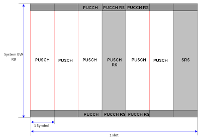
      The Uplink slot structure looks as follows. When I was first reading LTE materials, almost every books and article says "LTE use SC(Single Carrier) FDMA for uplink signal" and because of the word 'Single Carrier' made me so confused about creating any images of Uplink slot structure. Even now I don't think I can explain clearly about 'SC FDMA'. You may ask to FPGA or DSP engineer about the details of SC FDMA mechanism.

      But anyway good thing to me was that the most important factors in uplink slot is same as the one in the downlink. Just take a look at the overall uplink slot structure.


      As in downlink, Frame time and slot time in Uplink is the same as in the downlink. And the resource block structure is also same both in uplink and downlink. As shown above, 7 symbols in one slot is also the same in both uplink and downlink.
      A little bit of differences you would notice would be the location of the each channel. Normally in downlink case, a channel tend to lie across the whole bandwidth but the channels in the uplink slot seems to be more localized. For example, PUCCH is located only at the lowest and highest end in frequency domain and reference signals also localized in time domain or both timedomain and frequency domain.

      PUCCH RS

      Carries the Reference Signal that is required for demodulating PUCCH. It means if this part is not properly configured or eNodeB failed to detect this part, eNodeB cannot decode PUCCH.

      PUCCH

      This channel can carries a lot of information (UCI), but depending on the configuration it can carry only a few of the following information.

      • ACK/NACK for the recieved PDSCH data
      • CQI
      • RI
      • PMI

      As you see in the slot structure, PUCCH is located in the either extreme ends of the uplink frequency domain in alternating fashion between the two slots within a subframe, meaning that if the PUCCH is the lowest part of frequency domain in slot 0(first slot) and it will be located in the higest part of frequency domain in slot 1 (second slot). Exactly how many resource elements is allocated to the PUCCH is determined by network and the configuration is broadcasted to UE via SIB2.

      PUSCH RS

      Carries the Reference Signal that is required for demodulating PUCCH. It means if this part is not properly configured or eNodeB failed to detect this part, eNodeB cannot decode PUCCH. This is always located at the center of Uplink slot.

      PUSCH

      Carries Uplink data that UE tries to send. and it can also carries ACK/NACK for the PDSCH the UE recieved in addition to uplink data.

      Channels in Communication ==============