Tuesday, April 12, 2011
Wednesday, March 23, 2011
Exploring LTE MAC
I would be almost impossible to explain everything about LTE MAC in a single column without making it a thick book or without making everybody falling in sleep since MAC is the center of all LTE procedure. You would remember that I wrote a long column for RACH procedure, but that complicated procedure is just a small portion of LTE MAC procedure.
In this column, I would focus only on MAC overview and MAC PDU structure for SCH (data transmission and reception) and the other part of the MAC will be dealt in separate columns.
Let's start with overall MAC procedure. It is always good to use an illustration/diagram to give a big picture of anything.. but ironically it would be easily overlooked if we present something in diagram. So my recommendation is to try to convert the illustration into a verbal description and to convert a verbal description into a form of illustration. At least this kind of conversion process has helped me a lot.
Let's start this conversion with the following diagram from 36.321. You may have seen this from too many different LTE training material.. and overlooked it almost every time -:).

i) No BCCH, PCCH on Uplink path. (BCCH, PCCH is downlink only channels).
ii) UL CCCH, DCCH, DTCH are all mapped to UL-SCH.
iii) There is a special channel called 'RACH', but this does not have any corresponding logical channel.
Try this kind of 'reading' whenever you see any diagram.. very simple but it would really help.
MAC PDU Structure for SCH
Probably you would come across many cases where you have to analyze/manipulate this MAC PDU structure while you are doing troubleshooting or implementing the protocol stack.
For this, you have to refer to the following two sets of diagram at the same time. There would be many cases where you see a diagram and scratch your head trying to figure out the real meaning of the illustration. And then you will get the insight after you see another diagram.. and it would be after you spend a long time, a couple of weeks.. or several month .. even years.. asking "What the heck does this mean ?"
So my first tip to understand a diagram is "try to find another diagrams to help you to understand the one you now have".
Another tip is "get a real data (e.g, real data from UE or Network trace log) and try to analyze by hand according to the diagram".
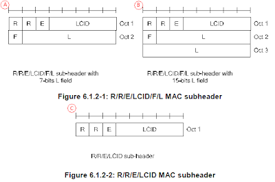

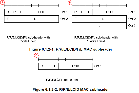
Let's understand the small keywords shown on the diagram. 36.321 6.2.1 MAC header for DL-SCH and UL-SCH has pretty good description.
i) R : R means 'Reserved", meaning that it does not have any special meaning for now. It is always set to be '0' for now.
ii) E : E means "Extension". This is set to '0' when the PDU marked as 'C' is used. If E is '1', 'A' or 'B' type of structure is used.
iii) LCID : LCID stands for "Logical Channel ID", meaning Logical Channel Number.
iv) F : F means 'Format'. This defines the length of 'L' field. If F is '0', the length of L field is 7 bit and if F is '1', the length of L field is 15 bit.
v) L : L means 'Length'. It shows the length of the MAC PDU. (Note that some MAC header, marked in 'C' does not have 'L' field. Then how can I know the length of MAC PDU, ie size of MAC PDU ? If there is no 'L' field, the size of MAC PDU is automatically set to be the same size of TBS(transport block size) in Byte unit.
In this column, I would focus only on MAC overview and MAC PDU structure for SCH (data transmission and reception) and the other part of the MAC will be dealt in separate columns.
Let's start with overall MAC procedure. It is always good to use an illustration/diagram to give a big picture of anything.. but ironically it would be easily overlooked if we present something in diagram. So my recommendation is to try to convert the illustration into a verbal description and to convert a verbal description into a form of illustration. At least this kind of conversion process has helped me a lot.
Let's start this conversion with the following diagram from 36.321. You may have seen this from too many different LTE training material.. and overlooked it almost every time -:).
 Let's just try to "read" (not "see") this illustration. I read as follows.
i) All the logical channes (PCCH, BCCH, CCCH, DCCH, DTCH) goes through MAC layer. (too simple reading ? -:)
ii) It seems that PCCH does not get manipulated by MAC in any special way. It just looks as if it is by passing MAC process. It does not use HARQ procedure meaning 'no retransmission' mechanism being used.
iii) CCCH, DCCH, DTCH all go through the same procedure (Prioritization, Mux/DeMux, HARQ).
iv) Some BCCH goes through HARQ, but some BCCH does not go through HARQ. Do you know which BCCH go through HARQ and which does not ? BCCH for MIB does not go through HARQ, but BCCH for SIB go through HARQ. (But this HARQ is a little different from normal HARQ that we know of.. It does not expecting any ACK/NACK response from the reciever.. but perform 'retransmission' based on a predefined rule).
v) Random Access process orignated within MAC layer, it does not have the correspoding logical channel. (This may apply to Msg1, Msg2 of RACH procedure.. Msg3,4,5 involves RRC layer intervention as well).
Let's read another important illustration from 36.321.
 I read as follows :
i) PCCH (Logical Channel) is mapped only to PCH (Transport channel).
ii) DL-CCCH, DCCH, DTCH are all mapped to DL-SCH.
iii) Some BCCH is mapped to BCH and Some BCCH is mapped to DL-SCH. Do you know which one is which ? BCCH for MIB is mapped to BCCH and BCCH for SIB is mapped to DL-SCH.
Let's do similar reading for Uplink channels as well.

i) No BCCH, PCCH on Uplink path. (BCCH, PCCH is downlink only channels).
ii) UL CCCH, DCCH, DTCH are all mapped to UL-SCH.
iii) There is a special channel called 'RACH', but this does not have any corresponding logical channel.
Try this kind of 'reading' whenever you see any diagram.. very simple but it would really help.
MAC PDU Structure for SCH
Probably you would come across many cases where you have to analyze/manipulate this MAC PDU structure while you are doing troubleshooting or implementing the protocol stack.
For this, you have to refer to the following two sets of diagram at the same time. There would be many cases where you see a diagram and scratch your head trying to figure out the real meaning of the illustration. And then you will get the insight after you see another diagram.. and it would be after you spend a long time, a couple of weeks.. or several month .. even years.. asking "What the heck does this mean ?"
So my first tip to understand a diagram is "try to find another diagrams to help you to understand the one you now have".
Another tip is "get a real data (e.g, real data from UE or Network trace log) and try to analyze by hand according to the diagram".

Let's understand the small keywords shown on the diagram. 36.321 6.2.1 MAC header for DL-SCH and UL-SCH has pretty good description.
i) R : R means 'Reserved", meaning that it does not have any special meaning for now. It is always set to be '0' for now.
ii) E : E means "Extension". This is set to '0' when the PDU marked as 'C' is used. If E is '1', 'A' or 'B' type of structure is used.
iii) LCID : LCID stands for "Logical Channel ID", meaning Logical Channel Number.
iv) F : F means 'Format'. This defines the length of 'L' field. If F is '0', the length of L field is 7 bit and if F is '1', the length of L field is 15 bit.
v) L : L means 'Length'. It shows the length of the MAC PDU. (Note that some MAC header, marked in 'C' does not have 'L' field. Then how can I know the length of MAC PDU, ie size of MAC PDU ? If there is no 'L' field, the size of MAC PDU is automatically set to be the same size of TBS(transport block size) in Byte unit.
Now all these in mind, let's try with my second tip saying "try to anlayze real data by hand". I have the following MAC PDU from my equipment trace log ..
03 45 00 00 3C 33 63 00 00 80 01 ....
The first step is to analyze the first byte. For this, let me convert the first byte into binary format as follows :
03 = 00000011
Let's rearrange these bits according to MAC PDU diagram as follows : (Bit number start from MSB meaning "start from left")
* Bit 0 = R field = 0
* Bit 1 = R field = 0
* Bit 2 = E field = 0. This means that this header does not have any 'Extension' and it means the this MAC PDU has the structure marked as 'C' (Figure 6.1.2-2)
* Bit 3~7 = LCID field = 11 in Binary = 3 in decimal. This means the logical channel number for this PDU is '3'.
This is the end of analysis. All the remaining part is user data.
Now let's try with another data as follows :
23 3C 1F 45 00 00 3C 33 63 00 00 80 01 ...
In the same way as above, let's try with the first byte, 23.
23 = 00100011
* Bit 0 = R field = 0
* Bit 1 = R field = 0
* Bit 2 = E field = 1. This means that this header does have some 'Extension' and it means the this MAC PDU has the structure marked as 'A' or 'B' (Figure 6.1.2-1). Then which one is the right one. A ? or B ? The answer comes later. Now the important thing is that you have to decode the second Byte as well since 'E' field is '1'.
* Bit 3~7 = LCID field = 11 in Binary = 3 in decimal. This means the logical channel number for this PDU is '3'.
Since 'E' field is set to '1'. We have to decode the second Byte as well.
3C = 00111100
Bit number continues from from the first byte.
* Bit 8 = F field = 0. This means that the size of L field is 7 bit.
* Bit 9~15 = L field = 0111100 = 60. This means the size of user data in this MAC PDU is 60 byte.
This is the end of second byte analysis. Is this all ? No.. when you have 'E' field to be '1'. You have to continue to decoding the header until you see the end.
Let's continue this analysis to the third byte, 1F as follows :
1F = 00011111
Process start from the begining because we know the first and second byte completes a complete header and I will restart the bit number as well.
* Bit 0 = R field = 0
* Bit 1 = R field = 0
* Bit 2 = E field = 0. It means that it does not have any 'extension'. It does not have any additional header. It means that this is the last header.
* Bit 3~7 = LCID = 11111. What does this mean ? If you see the table 6.2.1-1, 6.2.1-2.. this means 'MAC' padding. It means that this MAC PDU has MAC PDU after the user data. Then exactly which part is the padding and which part is the real user data. If you remember the first/second byte analysis, you should remember the size of real user data is 60 bytes. This, in turn, means that the data after the initial 60 bytes are the MAC padding.
Monday, March 7, 2011
Special Numbers in LTE
This is the first part of the long explanation which will take long time for me to complete. So this section would be the one with the least completion and will be updated most frequently for a while.
* SI-RNTI : It stands for System Information RNTI.
* RA-RNTI : It stands for Random Access RNTI
* C-RNTI : It stands for Cell RNTI
* TC-RNTI : It stands for Temporary C-RNTI
* SPS-C-RNTI : It stands for Semi persistance Scheduling C-RNTI
* TPC-PUCCH-RNTI : It stands for Transmit Power Control-Physical Uplink Control Channel-RNTI
* TPC-PUSCH-RNTI : It stands for Transmit Power Control-Physical Uplink Shared Channel-RNTI
* M-RNTI : It stands for MBMS RNTI
Who issues these RNTI ?
Network issues RNTI.
From 36.212 ---
5.3.3 Downlink control information
A DCI transports downlink or uplink scheduling information, or uplink power control commands for one RNTI. TheRNTI is implicitly encoded in the CRC.
This section explain in detail on how CRC is scrambled by RNTI
From 36.213 ---
5.1.1.1 UE behaviour
* δ_PUSCH is a UE specific correction value, also referred to as a TPC command and is included in PDCCH withDCI format 0 or jointly coded with other TPC commands in PDCCH with DCI format 3/3A whose CRC paritybits are scrambled with TPC-PUSCH-RNTI
* if the TPC command PUSCH δ_PUSCH is included in a PDCCH with DCI format 0 where the CRC is scrambled by the Temporary C-RNTI
* The UE attempts to decode a PDCCH of DCI format 0 with the UE’s C-RNTI or SPS CRNTI and a PDCCH of DCI format 3/3A with this UE’s TPC-PUSCH-RNTI in everysubframe
Reading through the specification and various materials about LTE, you would have came across so many different types of numbers. For example, Zadoff Chu sequence (actually this is not a single number, but a sequence of numbers), Cell ID, RNTIs etc. If you understand the exact practical meaning of these numbers and when and for what these numbers are used, you would understand LTE low layer processing more detail and this understanding would help you a lot when you implement protocol stack, test case and troubleshoot.
Zadoff - Chu Sequence
As I briefly mentioned above, this is not a single number. It is a sequence of special numbers. You can find quite a lot of materials on this sequence from internet (try with Wikipedia).
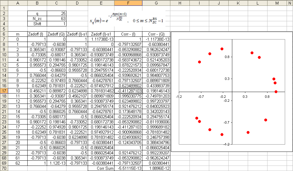
Let's first think about how this sequence is generated. Various kinds of number sequences are used in many different kind of technologies (e.g, Walsh code in CDMA, OVSF code in WCDMA) and usually these numbers are created by a special rules or formula. Same to Zadoff-Chu sequence. The basic form of Zadoff chu sequence can be created by the formula as shown in the following spreadsheet (click on the picture to see in magnified view. Please send me an email if you want to have this spreadsheet).
Why did we chose to use these sequence ? It is because this sequence has a couple of special properties that can be very useful for LTE low layer implementation.
Followings are the special properties of the sequence :
i) This sequence has a constant amplitude. If you look into the formula, it is in the form of e^(-j theta). You may learned about this in high school math. If you convert this into Euler form, you will get e^(-j theta) = cos(theta) - j sin(theta). First, you will see this is a complex number which is made up of real and imaginary part. If you plot the numbers onto a complex plan (Real part - horizontal axis and Imaginary part on vertical axis), all the numbers will lie on the perimeter of a circle. This means the amplitude of these number is constant. See the plot above. (Column B, C is one example of Zadoff Sequence. B is the real part and C is imaginary part. The plot is the scatter plot of column B, C)
ii) Zero Autocorrelation. If you create a sequence using this formula and create another sequence just by shifting the same sequence by N (N can be 1,2,....,size of sequence -1). And if you take the correlation of the two sequence, the result become 0. Taking the spreadsheet shown above as an example, Column B,C is a sequence created by formula. and Column D,E is not the one created by the formula.. it is just shifted version of Column B, C. Cell F70 and G70 shows the correlation of Column B,C and D,E which gives almost 0. It should be 0 theoretically, but the F70,G70 is not exactly 0 because of numerical errors.. but it is almost 0. If you have two sequence of number and the correlation of the two sequence is 0, we say "the two sequences are orthogonal to each other". It means that you can create many of orthogonal sequences just by shifting a Zadoff Chu sequence. How convenient it is to create orthogonal sequences.. and you know how important to create orthogonal sequences in many wireless communication.
Any sequences that has the two properties explained above are called CAZAC sequence (constant amplitude zero autocorrelation waveform).
iii) Cross correlation of two Zadoff Chu sequence is 1/Sqrt(Nzc). If you create two sequences using the formula shown on the spreadsheet just by changing 'q' (the q value used in both sequence should be prime numbers) and take the correlation of the two sequences, the result will be 1/Sqrt(Nzc).
There are a couple of more special properties of Zadoff Chu sequences, but I don't think they are important for LTE implementation. So I would leave it to you to refer to other sources.
Where in LTE we use this Zaddoff Chu sequence. In short, the sequence are used in the following part of LTE. (I will update the details of these topics later)
i) Primary Synchronization Signal (PSS) (so called primary synchronization channel)
ii) random access preamble (PRACH)
iii) HARQ ACK/NACK responses (PUCCH)
iv) sounding reference signals(SRS).
RNTI
One of the other numbers which you would very frequently come accross is RNTI. RNTI stands for Radio Network Temporary Identifier.
As the name implies, it is a kind of Identification number. Normally we use indentification number to differntiate one thing from all other similar things. For example, your driver's license number let you identify yourself from all other drivers. Social Security number do the same thing as well.
Getting more specifically into LTE, this RNTI is used to indentify one specific radio channel from other radio channel and one user from another user. As you may recall, in WCDMA is a RNTI concept which is carried as part of MAC header to deferentiate one user to another while in communication state. and in WCDMA case it used special channelization code to deferentiate one radio channel from the other.
To my personal perception, RNTI in LTE seems to act as combined role of WCDMA RNTI and WCDMA channelization code (but RNTI has nothing to do with orthogonality.. so this is very superfical analogy. Just take this as an analogy just for understanding high level functionality).
What kind of RNTIs are there in LTE ?
The answer is A LOT -:). Followings are the brief summary of RNTIs being used in LTE. More detailed explanation will be updated continuously later.
* SI-RNTI : It stands for System Information RNTI.
* RA-RNTI : It stands for Random Access RNTI
* C-RNTI : It stands for Cell RNTI
* TC-RNTI : It stands for Temporary C-RNTI
* SPS-C-RNTI : It stands for Semi persistance Scheduling C-RNTI
* TPC-PUCCH-RNTI : It stands for Transmit Power Control-Physical Uplink Control Channel-RNTI
* TPC-PUSCH-RNTI : It stands for Transmit Power Control-Physical Uplink Shared Channel-RNTI
* M-RNTI : It stands for MBMS RNTI
Who issues these RNTI ?
Network issues RNTI.
Exactly what does RNTI do for each of those radio channel ? The detailed process differs with the types of RNTIs, but generally speaking all of these RNTI is used to scramble the CRC part of the radio channel messages. It implies that if UE does not know the exact RNTI values for each of the cases, it cannot decode the radio channel messages even though the message reaches the UE intact.
Following is the quotes from 3GPP specification showing how RNTI is used for various cases.. for the exact details, you should see the specification but this partial quote would give you a rough idea of the usage of RNTI.From 36.212 ---
5.3.3 Downlink control information
A DCI transports downlink or uplink scheduling information, or uplink power control commands for one RNTI. TheRNTI is implicitly encoded in the CRC.
5.3.3.1.3 Format 1A
Format 1A is used for random access procedure initiated by a PDCCH order only if format 1A CRC is scrambledwith C-RNTI
For distributed VRB: .. if the format 1A CRC is scrambled by RA-RNTI, P-RNTI, or SI-RNTI
5.3.3.2 CRC attachment
This section explain in detail on how CRC is scrambled by RNTI
From 36.213 ---
5.1.1.1 UE behaviour
* δ_PUSCH is a UE specific correction value, also referred to as a TPC command and is included in PDCCH withDCI format 0 or jointly coded with other TPC commands in PDCCH with DCI format 3/3A whose CRC paritybits are scrambled with TPC-PUSCH-RNTI
* if the TPC command PUSCH δ_PUSCH is included in a PDCCH with DCI format 0 where the CRC is scrambled by the Temporary C-RNTI
* The UE attempts to decode a PDCCH of DCI format 0 with the UE’s C-RNTI or SPS CRNTI and a PDCCH of DCI format 3/3A with this UE’s TPC-PUSCH-RNTI in everysubframe
5.1.2.1 UE behaviour
δ_PUCCH is a UE specific correction value, also referred to as a TPC command, included in a PDCCH with DCIformat 1A/1B/1D/1/2A/2 or sent jointly coded with other UE specific PUCCH correction values on a PDCCHwith DCI format 3/3A whose CRC parity bits are scrambled with TPC-PUCCH-RNTI.
o The UE attempts to decode a PDCCH of DCI format 3/3A with the UE’s TPC-PUCCH-RNTI and oneor several PDCCHs of DCI format 1A/1B/1D/1/2A/2 with the UE’s C-RNTI or SPS C-RNTI onevery subframe except when in DRX.
o If the UE decodes a PDCCH with DCI format 1A/1B/1D/1/2A/2 and the corresponding detectedRNTI equals the C-RNTI or SPS C-RNTI of the UE, the UE shall use the δ PUCCH provided in that PDCCH.
6.1 Physical non-synchronized random access procedure
* A preamble index, a target preamble received power (PREAMBLE_RECEIVED_TARGET_POWER), acorresponding RA-RNTI and a PRACH resource are indicated by higher layers as part of the request.
* Detection of a PDCCH with the indicated RA-RNTI is attempted during a window controlled by higher layers
7.1 UE procedure for receiving the physical downlink shared channel
* If a UE is configured by higher layers to decode PDCCH with CRC scrambled by the SI-RNTI, the UE shall decode thePDCCH and the corresponding PDSCH according to any of the combinations defined in table 7.1-1. The scramblinginitialization of PDSCH corresponding to these PDCCHs is by SI-RNTI.
* If a UE is configured by higher layers to decode PDCCH with CRC scrambled by the P-RNTI, the UE shall decode thePDCCH and the corresponding PDSCH according to any of the combinations defined in table 7.1-2. The scramblinginitialization of PDSCH corresponding to these PDCCHs is by P-RNTI.
* If a UE is configured by higher layers to decode PDCCH with CRC scrambled by the C-RNTI, the UE shall decode thePDCCH and any corresponding PDSCH according to the respective combinations defined in table 7.1-5. Thescrambling initialization of PDSCH corresponding to these PDCCHs is by C-RNTI.
* If a UE is configured by higher layers to decode PDCCH with CRC scrambled by the Temporary C-RNTI and is notconfigured to decode PDCCH with CRC scrambled by the C-RNTI, the UE shall decode the PDCCH and thecorresponding PDSCH according to the combination defined in table 7.1-7. The scrambling initialization of PDSCHcorresponding to these PDCCHs is by Temporary C-RNTI.
Sunday, March 6, 2011
Power Control
When we study a new technology.. one of way to efficiently learn/understand about it would be to assume that you are the designer/developer of the technology and ask yourself "Now I have this and this problem in such and such situation. How can I resolve the issue ?". If you keep asking the same questions to yourself, you would have some form of answer even though it may not be technically in detail and it may not be the solution that is really being used in the field. But don't be discouraged.. there is no absolute solutions for most of those problems.. probably your answer would be better than the one that is really being used.
Now I will talk about the power control issues in LTE.
Then how do solve the problem ? This is the time that you assume you become a designer and have to come up with an idea to solve this issue.How do you handle this situation ?
The simplest way would be to use a very high gain amplifier on transmitter and blast huge powered signal to reciever.This method would be good when the reciever and the transmitter is in a reasonable distance. But what if the distance between reciever and transmitter is too close ? In this case, the strong signal from the transmitter may saturate the reciever.
Then how do you handle this situation ? You may try to tune down the transmitter amplifier power so that the receiver does not get saturated. If the distance between transmitter and reciever does not change and the channel condition (Humidity, precipitation, buildings) does not change, this kind of manual tuning would work. But can we do the same thing with mobile communication where the distance between reciever and transmitter changes very often and channel condition changes as well.
Now you have think up a solution to cope with this kind of varying distance and changing channel condition.
The way the people in this area came out is as follows :
i) Transmit send a signal to reciever
ii) Reciever measure the power of the signal from the transmitter
iii) if the measured power is too low, the reciever send a special command saying "increase the power". And if the measured power is too strong, it would send another command saying "decrease the power".
By this mechanism, the transmitter can change it's output power dynamically. This kind of power control mechanism is often called "Closed Loop Power Control" and the special command being used for power control is called TPC (Transmit Power Control) command. In short, Transmit send something and the reciever send a feedback to the transmitter and the reciever retunes itself by the feedback. This whole process forms a cyclic loop and this kind of control loop is called "Closed Loop" in control system theory.This kind of power control is used in almost all the mobile communication technology (e.g, CDMA, WCDMA, LTE and even in Bluetooth etc). This kind of power control process happens much more frequently than you may think. For example, in WCDMA case it would happen around 1500 times maximum within a second ideally. and in LTE case it can happen maximum 1000 times within a second.
If you are a person who is really interested in the power control mechanism and thought in very details about various communication environment, you may notice that there is a situation where we cannot use this kind of "command based power control" method. The 'command based power control'mechansm is based on a asumption that the transmitter and reciever has already established a call setup so thta they can exchange these command.
What if the transmitter and reciever is not in such a communication state ? For example, you just turned on your mobile phone and the mobile phone (transmitter in this case) has to send some signal to the base station (the reciever in this case).
How strong power the mobile phone has to transmit it's first signal ?This is very important.. if the mobile phone transmit the signal in too low power, the base station would not detect it.. and if it transmit it in too high power, it can interfere with the communication between other mobile phone and the base station. So it has to determine the proper transmit power level which would be strong enough to be properly decoded by the base station and weak enough not to interfere the communication between other mobile phone and the base station.
How do you handle this situation ? What kind of method the UE should use to determin the proper transmission power ?
It would not be easy to think out a solution intuitively...
Overall logic that is commonly used in mobile phone communication system is as follows :
i) Network (Base Station) is tranmitting a certain reference signal with a fixed power value
ii) Network transmit the information (e.g, Power) about the reference signal it is transmitting
iii) Network also transmit the maximum allowable power that UE can transmit.
iv) UE decode the reference signal comming from the base station and measured the power.
v) UE can figure out the path loss between the UE and base station by comparing the result of step iv) and step ii).
vi) Also from the information at step ii), UE knows how much power is allowed for it.
vii) From the result at step v) and step vi), UE can figure out how much power it can really transmit.
This kind of process is also called a power control process. But since this power determination process is not based on a feedback loop as in Closed Loop Power Control, it is called "Open Loop Power Control".
Power Control in LTE
For details of LTE specific power control, you have to refer to
"TS 36.213 - 5. Power Control" and if you want to have some hands-on experience of these, I would recommand you to try some test items on 36.521.
For PRACH Power, refer to "TS 36.213 - 6.1 Physical non-synchronized random access procedure".
Power Control in LTE can be summerized by the following equations. The main purpose for this section is to understand the every details of these equations.
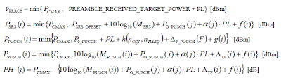 Since it is not easy to embed the mathematical symbols in this blog, I would express these symbols in text form as shown below.
 Let me continue later on these details. Stay tuned -:)
Now I will talk about the power control issues in LTE.
Before we go into the LTE specific power control, let's try with our own thought process for this power control issue. In wired communication, the amount of energy (power) being sent from the transmitter reachs the reciever without much degradation. Just think about connecting two PC with a long ethernet cable (e.g, around 10 m) and connecting a device to your PC with a simple RS 232 cables (usually less than 2 m). If you measure the voltage at the two ends of the cables while communicating, you will not see much voltage drops between the source and the destination. (Of course there is a certain amount of voltage drops. but the drop is not so big that it cannot be recognized by the reciever). However, what if the transmitter and reciever is connected wirelessly ?
You can intuitively know that the energy drop will be tremandous. Anybody who tried to measure something wirelessly (e.g, test a mobile phone with antenna, not with cable connection with Network simulator or spectrum analyzer) would have experienced these energy drop every time they do the test.Then how do solve the problem ? This is the time that you assume you become a designer and have to come up with an idea to solve this issue.How do you handle this situation ?
The simplest way would be to use a very high gain amplifier on transmitter and blast huge powered signal to reciever.This method would be good when the reciever and the transmitter is in a reasonable distance. But what if the distance between reciever and transmitter is too close ? In this case, the strong signal from the transmitter may saturate the reciever.
Then how do you handle this situation ? You may try to tune down the transmitter amplifier power so that the receiver does not get saturated. If the distance between transmitter and reciever does not change and the channel condition (Humidity, precipitation, buildings) does not change, this kind of manual tuning would work. But can we do the same thing with mobile communication where the distance between reciever and transmitter changes very often and channel condition changes as well.
Now you have think up a solution to cope with this kind of varying distance and changing channel condition.
The way the people in this area came out is as follows :
i) Transmit send a signal to reciever
ii) Reciever measure the power of the signal from the transmitter
iii) if the measured power is too low, the reciever send a special command saying "increase the power". And if the measured power is too strong, it would send another command saying "decrease the power".
By this mechanism, the transmitter can change it's output power dynamically. This kind of power control mechanism is often called "Closed Loop Power Control" and the special command being used for power control is called TPC (Transmit Power Control) command. In short, Transmit send something and the reciever send a feedback to the transmitter and the reciever retunes itself by the feedback. This whole process forms a cyclic loop and this kind of control loop is called "Closed Loop" in control system theory.This kind of power control is used in almost all the mobile communication technology (e.g, CDMA, WCDMA, LTE and even in Bluetooth etc). This kind of power control process happens much more frequently than you may think. For example, in WCDMA case it would happen around 1500 times maximum within a second ideally. and in LTE case it can happen maximum 1000 times within a second.
If you are a person who is really interested in the power control mechanism and thought in very details about various communication environment, you may notice that there is a situation where we cannot use this kind of "command based power control" method. The 'command based power control'mechansm is based on a asumption that the transmitter and reciever has already established a call setup so thta they can exchange these command.
What if the transmitter and reciever is not in such a communication state ? For example, you just turned on your mobile phone and the mobile phone (transmitter in this case) has to send some signal to the base station (the reciever in this case).
How strong power the mobile phone has to transmit it's first signal ?This is very important.. if the mobile phone transmit the signal in too low power, the base station would not detect it.. and if it transmit it in too high power, it can interfere with the communication between other mobile phone and the base station. So it has to determine the proper transmit power level which would be strong enough to be properly decoded by the base station and weak enough not to interfere the communication between other mobile phone and the base station.
How do you handle this situation ? What kind of method the UE should use to determin the proper transmission power ?
It would not be easy to think out a solution intuitively...
Overall logic that is commonly used in mobile phone communication system is as follows :
i) Network (Base Station) is tranmitting a certain reference signal with a fixed power value
ii) Network transmit the information (e.g, Power) about the reference signal it is transmitting
iii) Network also transmit the maximum allowable power that UE can transmit.
iv) UE decode the reference signal comming from the base station and measured the power.
v) UE can figure out the path loss between the UE and base station by comparing the result of step iv) and step ii).
vi) Also from the information at step ii), UE knows how much power is allowed for it.
vii) From the result at step v) and step vi), UE can figure out how much power it can really transmit.
This kind of process is also called a power control process. But since this power determination process is not based on a feedback loop as in Closed Loop Power Control, it is called "Open Loop Power Control".
Power Control in LTE
For details of LTE specific power control, you have to refer to
"TS 36.213 - 5. Power Control" and if you want to have some hands-on experience of these, I would recommand you to try some test items on 36.521.
For PRACH Power, refer to "TS 36.213 - 6.1 Physical non-synchronized random access procedure".
Power Control in LTE can be summerized by the following equations. The main purpose for this section is to understand the every details of these equations.
 Since it is not easy to embed the mathematical symbols in this blog, I would express these symbols in text form as shown below.
 Let me continue later on these details. Stay tuned -:)
Thursday, March 3, 2011
Paging
Paging is the mechanism in which Network tells UE saying "I have something for you". Then UE decode the content (Paging Cause) of the Paging message and UE has to initiate the appropriate the procedure.
In most cases, this paging process happens while UE is in idle mode. This means that UE has to monitor whether the networking is sending any paging message to it and it has to spend some energy(battery) to run this "Monitoring" process.
If I have to run this "Monitoring" process continously even in the idle mode, isn't it too much waste of engergy ?Yes, it is.
Is there any way to prevent this kind of energy waste ? There would be no way to prevent this envergy consumption completely (if you can come out with any idea to prevent this completely, you don't need to read this any more.. just do early retire and enjoy your life whereever you want to go with huge money coming out of your patent -:), but there would be some way to reduce the consumption in great degree.What is it ? There may be many different way to do this.. but most common method (probably easiest to realize) is to make some 'contract' between UE and Network.What kind of contract it would be like ? It is like "Hey.. Mr. Net.. don't send the paging method continuously.. just transmit it in a kind of burst mode with a certain interval. I will go sleep when you are not transmitting Paging and I will just wake up exactly at the time you are transmitting the paging message".This way UE can save the battery while it is in sleep and can get the paging message as well. It means that UE is recieving some data from the network "discontinously". This kind of reception mechanism is called DRX (Discontinous Reception).Here we have an important question. How can UE knows the exact timing when the Network send the paging ? The simplest solution for this would be to make another contract about "Paging transmission timing". you see the logic ?
Now it's time to get into the official specification.
There are two most important terminologies which is PF(Paging Frame) and PO(Paging Occasion). 3GPP 36.304 - [7 Paging] explain this two terms as follows :
* Occasion (PO) is a subframe where there may be P-RNTI transmitted on PDCCH addressing the paging message.
* Paging Frame (PF) is one Radio Frame, which may contain one or multiple Paging Occasion(s).
As you know, LTE has two timing units as many of other technology. Timing Unit in Frame scale (SFN : System Frame Number) is one unit and the timing unit in subframe level (Subframe Number). It means that you have to know both SFN and Subframe Number to locate exact position in LTE time domain. Regarding the paging cycle, PF(Paging Frame) + PO(Paging Occasion) let you know the exact timing when UE has to wake up to catch the paging message being sent to it.
Let's tackle the PF first.
PF = SFN mod T = (T div N) x (UE_ID mod N)
Then where does T come from ? According to 34.104, T is defined as follows :
T is DRX cycle of the UE. T is determined by the shortest of the UE specific DRX value, if allocated by upperlayers, and a default DRX value broadcast in system information . If UE specific DRX is not configured by upperlayers, the default value is applied.
It means UE can get the T from two different source, one from the system information (SIB2, IE defaultPagingCycle) and the one from upper layer. Then which value does UE has to use ? It depends on the situation. If upper layer send the value, it use the value from the uppder layer, otherwise UE has to use the value from SIB2.
Then let's think about where does other values come from. These values are defined as follows in the specification.
N = min(T, nB), which means the smaller one among T and nB.
nB can be any one of 4T, 2T, T/2, T/4, T/8, T/16, T/32, which comes from SIB2 (IE nB).
UE_ID = IMSI mod 1024, where IMSI should be used in Decimal format and is stored in USIM.
By this, we got PF now. Then what is the next step ? We have to get PO (Paging Occasion).
34.104 defines PO as follows :

From the table, we can figure out PO if we get i_s. Then how to get i_s ?
We already explained how to get N. We only have to know Ns now. 36.104 defines Ns as follows:
Ns = max(1, nB/T), which means that Ns is the larger value between 1 and NB/T.
Subscribe to:
Comments (Atom)