In this column, I would focus only on MAC overview and MAC PDU structure for SCH (data transmission and reception) and the other part of the MAC will be dealt in separate columns.
Let's start with overall MAC procedure. It is always good to use an illustration/diagram to give a big picture of anything.. but ironically it would be easily overlooked if we present something in diagram. So my recommendation is to try to convert the illustration into a verbal description and to convert a verbal description into a form of illustration. At least this kind of conversion process has helped me a lot.
Let's start this conversion with the following diagram from 36.321. You may have seen this from too many different LTE training material.. and overlooked it almost every time -:).
 Let's just try to "read" (not "see") this illustration. I read as follows.
i) All the logical channes (PCCH, BCCH, CCCH, DCCH, DTCH) goes through MAC layer. (too simple reading ? -:)
ii) It seems that PCCH does not get manipulated by MAC in any special way. It just looks as if it is by passing MAC process. It does not use HARQ procedure meaning 'no retransmission' mechanism being used.
iii) CCCH, DCCH, DTCH all go through the same procedure (Prioritization, Mux/DeMux, HARQ).
iv) Some BCCH goes through HARQ, but some BCCH does not go through HARQ. Do you know which BCCH go through HARQ and which does not ? BCCH for MIB does not go through HARQ, but BCCH for SIB go through HARQ. (But this HARQ is a little different from normal HARQ that we know of.. It does not expecting any ACK/NACK response from the reciever.. but perform 'retransmission' based on a predefined rule).
v) Random Access process orignated within MAC layer, it does not have the correspoding logical channel. (This may apply to Msg1, Msg2 of RACH procedure.. Msg3,4,5 involves RRC layer intervention as well).
Let's read another important illustration from 36.321.
 I read as follows :
i) PCCH (Logical Channel) is mapped only to PCH (Transport channel).
ii) DL-CCCH, DCCH, DTCH are all mapped to DL-SCH.
iii) Some BCCH is mapped to BCH and Some BCCH is mapped to DL-SCH. Do you know which one is which ? BCCH for MIB is mapped to BCCH and BCCH for SIB is mapped to DL-SCH.
Let's do similar reading for Uplink channels as well.

i) No BCCH, PCCH on Uplink path. (BCCH, PCCH is downlink only channels).
ii) UL CCCH, DCCH, DTCH are all mapped to UL-SCH.
iii) There is a special channel called 'RACH', but this does not have any corresponding logical channel.
Try this kind of 'reading' whenever you see any diagram.. very simple but it would really help.
MAC PDU Structure for SCH
Probably you would come across many cases where you have to analyze/manipulate this MAC PDU structure while you are doing troubleshooting or implementing the protocol stack.
For this, you have to refer to the following two sets of diagram at the same time. There would be many cases where you see a diagram and scratch your head trying to figure out the real meaning of the illustration. And then you will get the insight after you see another diagram.. and it would be after you spend a long time, a couple of weeks.. or several month .. even years.. asking "What the heck does this mean ?"
So my first tip to understand a diagram is "try to find another diagrams to help you to understand the one you now have".
Another tip is "get a real data (e.g, real data from UE or Network trace log) and try to analyze by hand according to the diagram".
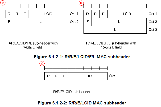

Let's understand the small keywords shown on the diagram. 36.321 6.2.1 MAC header for DL-SCH and UL-SCH has pretty good description.
i) R : R means 'Reserved", meaning that it does not have any special meaning for now. It is always set to be '0' for now.
ii) E : E means "Extension". This is set to '0' when the PDU marked as 'C' is used. If E is '1', 'A' or 'B' type of structure is used.
iii) LCID : LCID stands for "Logical Channel ID", meaning Logical Channel Number.
iv) F : F means 'Format'. This defines the length of 'L' field. If F is '0', the length of L field is 7 bit and if F is '1', the length of L field is 15 bit.
v) L : L means 'Length'. It shows the length of the MAC PDU. (Note that some MAC header, marked in 'C' does not have 'L' field. Then how can I know the length of MAC PDU, ie size of MAC PDU ? If there is no 'L' field, the size of MAC PDU is automatically set to be the same size of TBS(transport block size) in Byte unit.
Now all these in mind, let's try with my second tip saying "try to anlayze real data by hand". I have the following MAC PDU from my equipment trace log ..
03 45 00 00 3C 33 63 00 00 80 01 ....
The first step is to analyze the first byte. For this, let me convert the first byte into binary format as follows :
03 = 00000011
Let's rearrange these bits according to MAC PDU diagram as follows : (Bit number start from MSB meaning "start from left")
* Bit 0 = R field = 0
* Bit 1 = R field = 0
* Bit 2 = E field = 0. This means that this header does not have any 'Extension' and it means the this MAC PDU has the structure marked as 'C' (Figure 6.1.2-2)
* Bit 3~7 = LCID field = 11 in Binary = 3 in decimal. This means the logical channel number for this PDU is '3'.
This is the end of analysis. All the remaining part is user data.
Now let's try with another data as follows :
23 3C 1F 45 00 00 3C 33 63 00 00 80 01 ...
In the same way as above, let's try with the first byte, 23.
23 = 00100011
* Bit 0 = R field = 0
* Bit 1 = R field = 0
* Bit 2 = E field = 1. This means that this header does have some 'Extension' and it means the this MAC PDU has the structure marked as 'A' or 'B' (Figure 6.1.2-1). Then which one is the right one. A ? or B ? The answer comes later. Now the important thing is that you have to decode the second Byte as well since 'E' field is '1'.
* Bit 3~7 = LCID field = 11 in Binary = 3 in decimal. This means the logical channel number for this PDU is '3'.
Since 'E' field is set to '1'. We have to decode the second Byte as well.
3C = 00111100
Bit number continues from from the first byte.
* Bit 8 = F field = 0. This means that the size of L field is 7 bit.
* Bit 9~15 = L field = 0111100 = 60. This means the size of user data in this MAC PDU is 60 byte.
This is the end of second byte analysis. Is this all ? No.. when you have 'E' field to be '1'. You have to continue to decoding the header until you see the end.
Let's continue this analysis to the third byte, 1F as follows :
1F = 00011111
Process start from the begining because we know the first and second byte completes a complete header and I will restart the bit number as well.
* Bit 0 = R field = 0
* Bit 1 = R field = 0
* Bit 2 = E field = 0. It means that it does not have any 'extension'. It does not have any additional header. It means that this is the last header.
* Bit 3~7 = LCID = 11111. What does this mean ? If you see the table 6.2.1-1, 6.2.1-2.. this means 'MAC' padding. It means that this MAC PDU has MAC PDU after the user data. Then exactly which part is the padding and which part is the real user data. If you remember the first/second byte analysis, you should remember the size of real user data is 60 bytes. This, in turn, means that the data after the initial 60 bytes are the MAC padding.